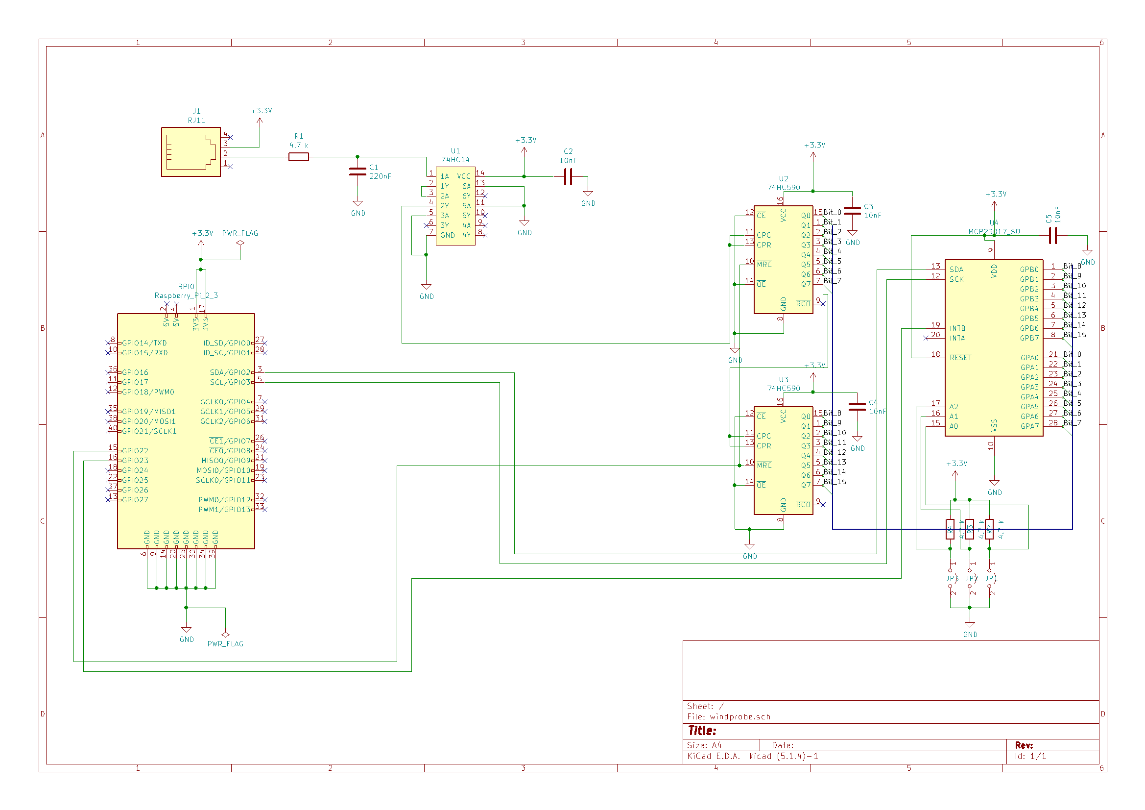
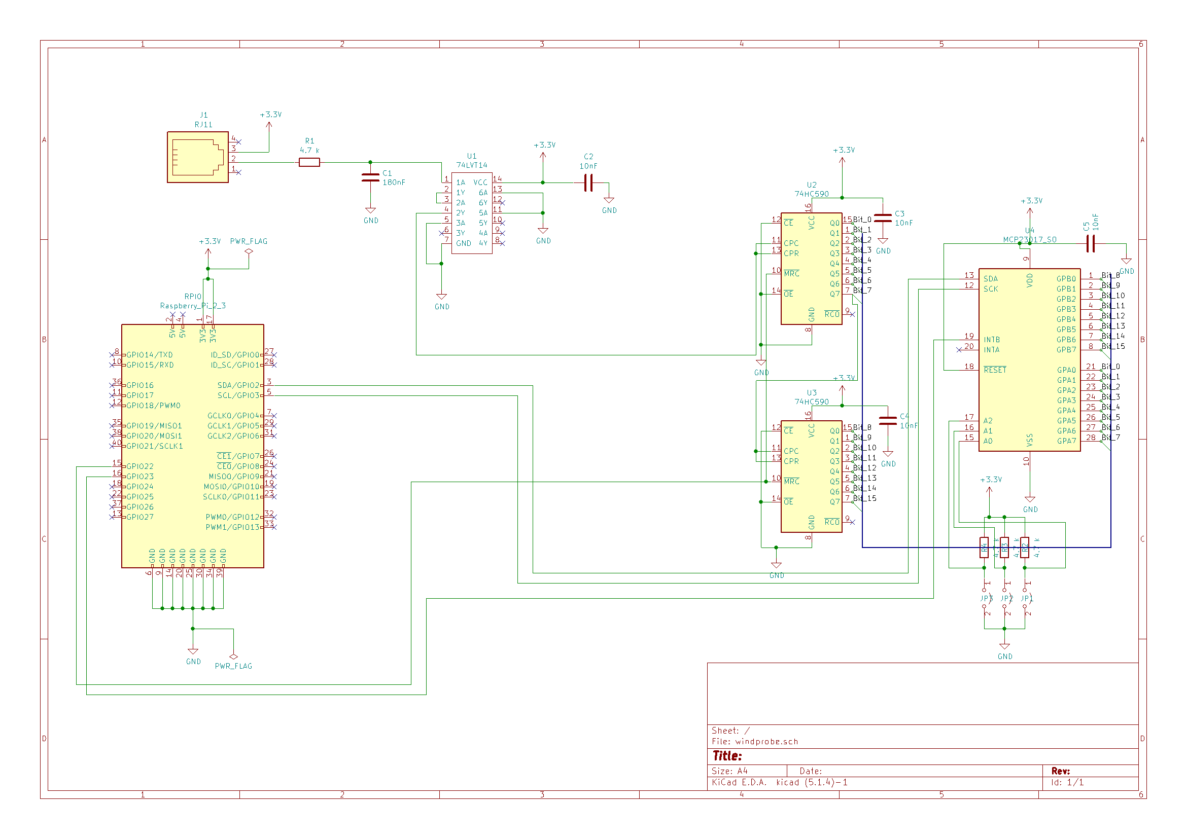
A complete list (we think) for the lab test components is under the meteo project folder (Test_Lab_Shopping_list.xlsx) and listed later in the blog. Also we had to change a capacitor value (from 180nf to 220nf) and the schmitt trigger because it is very hard to find these items. We updated the schema accordingly. We didn’t have time to go into detail how the mcp23017 interruptor works, thats up for the next time. But it looks very promising that the mcp23017 i/o expander is as customizable as we want it.

Here is a first shopping list. It’s important to note that it is a mix of windprobe specific items, project specific, general tools and test setup. If everything works out as planned I will create a project only shopping list with the exact parts needed.
Windprobe specific (mostly)
- Meteo station 68€
- 74HC14 7.40€
- Serie E24 Resistors 2x 14.62€
- Ceramic Capacitors 12€
- Serie E24 Capacitors 19€
- 74HC590 10x 0.8€
- MCP23017 18.81€
- RJ45-Breakout 10.2€
General items or tools for either testing or for the entire station.
- Labtest connectors 7€
- Dupont Connector kit 37€
- Labtest Board 30.8€
- Lab test raspberry breakout 7€
- POE Switch 40€
- RPI-4 starter kit 105€
- RPI-POE 18.4€
- Labtest connectors 7€
As always, the Github is here: https://github.com/TheCell/Weatherstation

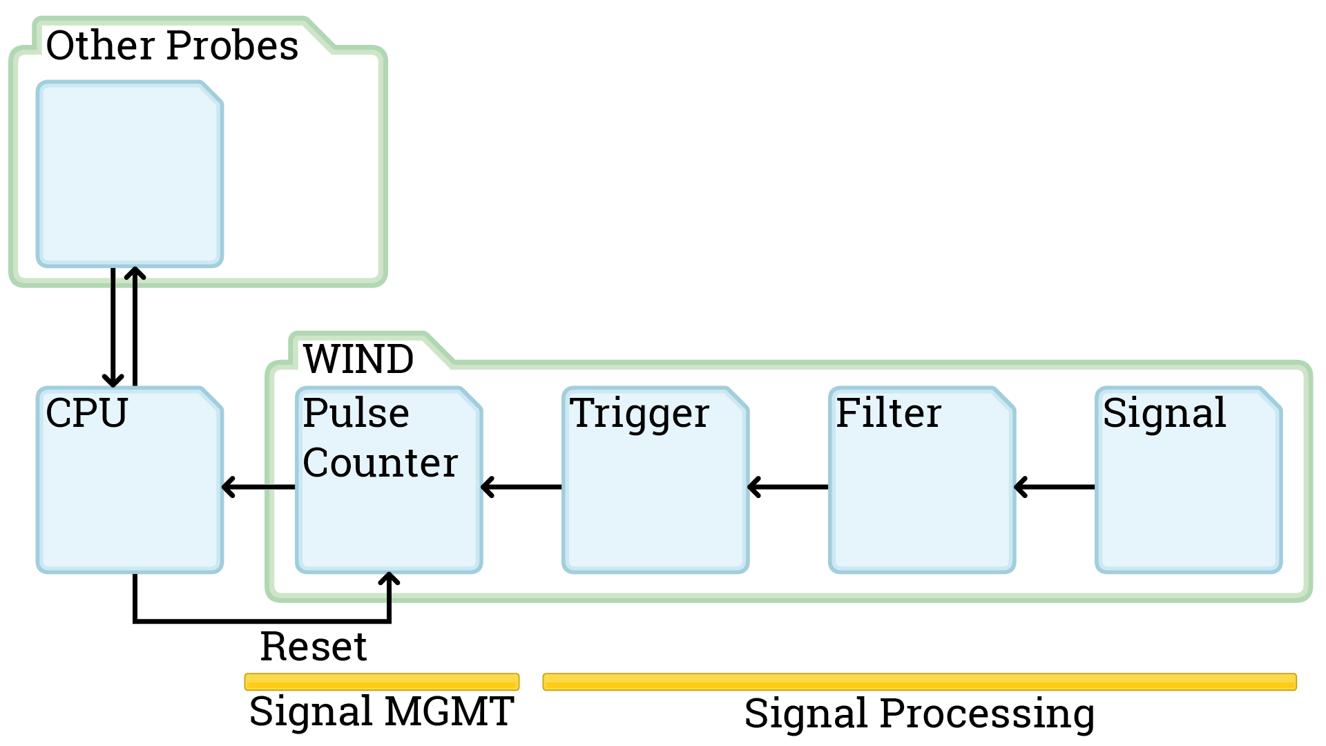
This Session we finalized the schematics for the windprobe. The Diagram shown is tested in kicad and the electrical connections are all good. We changed how the interruptors are handled and what gets managed by the Raspberry. The Signal Management works over a I²C bus now.

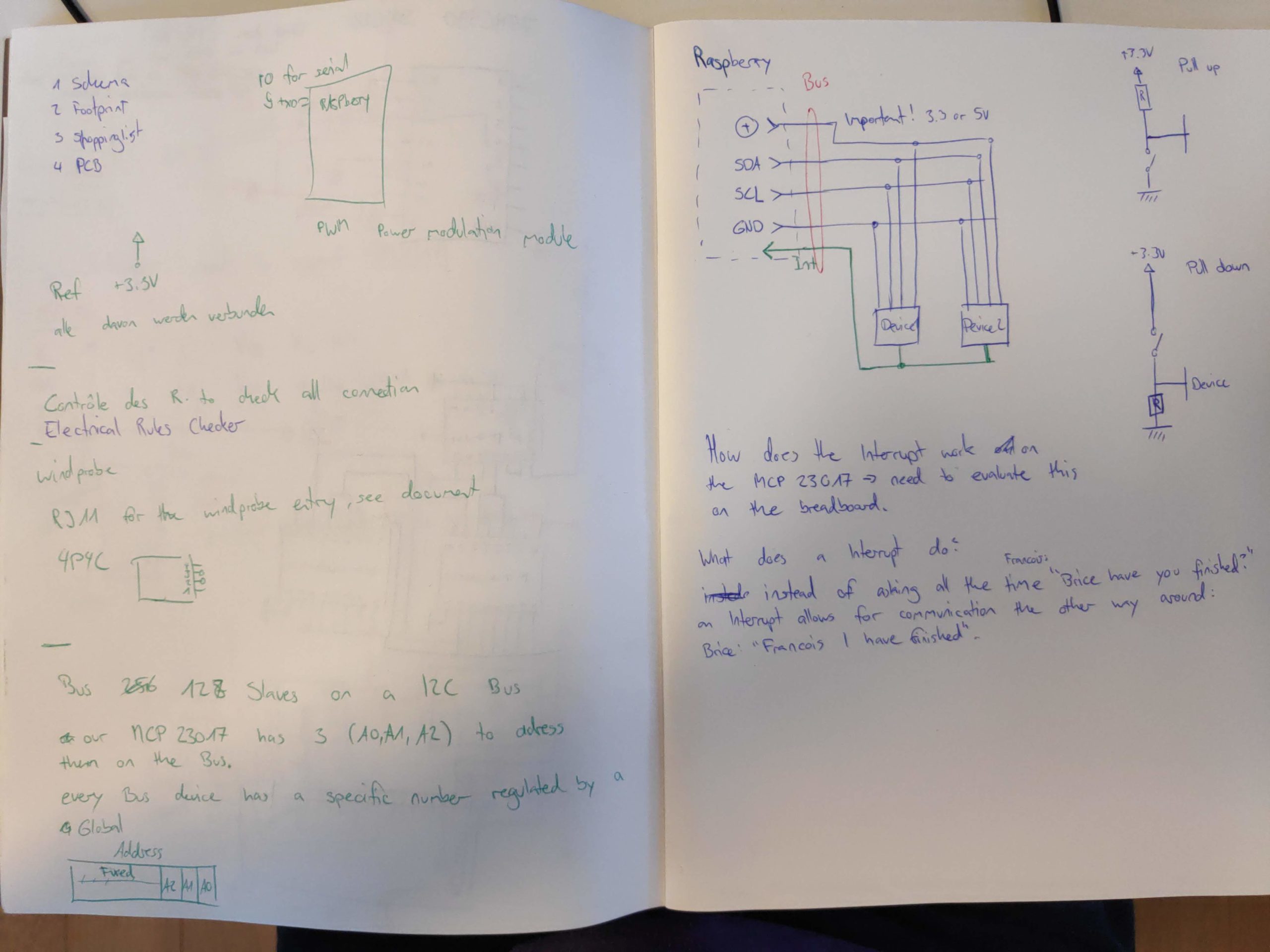
What is I²C and how does I²C work? I²C is a data bus protocol that allows us to have multiple probes communicating via I/O expander over the same line to the raspberry. More details can be found on Wikipedia.
First of all, how do we know which I/O expander is sending the data to the raspberry? We take a look at the MCP23017 Datasheet and we look at the A0 to A2 pins. The Datasheet (found in the github repo) on page 15 gives more details: Our Device has a 7 bit slave addressing. 4 fixed bits, 3 user-defined (A0 – A2). With these we can have multiple different I/O expander on the same line and identify every one of these separately. If you take a look at the bottom right of the schema, that’s why there are jumpers drawn there. When we set the jumper configuration differently on all I/O expanders on the same line we always know which device we are talking to.

Now for the communication: How the communication works is very well explained in this video starting at 7 min 20 s. The embeded video should start at that time.
We will take a look at how everything is programmed later on when we have the parts and have everything working on a breadboard.

Archives
- November 2023
- December 2022
- November 2022
- February 2022
- November 2021
- October 2021
- September 2021
- July 2021
- April 2021
- March 2021
- February 2021
- January 2021
- September 2020
- July 2020
- April 2020
- March 2020
- February 2020
- December 2019
- November 2019
- October 2019
- August 2019
- June 2019
- February 2019
- December 2018
- November 2018
- October 2018
- September 2018
- August 2018
- July 2018
- May 2018
- March 2018
- February 2018
- December 2017
- November 2017
- September 2017
- July 2017
- June 2017
- April 2017
- February 2017
- January 2017
- October 2016
- September 2016
- July 2016
- May 2016
- April 2016
- March 2016
- August 2015
- July 2015
- May 2015
- April 2015
- March 2015
- February 2015
- January 2015
- October 2014
- April 2014
- March 2014
- February 2014
